PVEL’s Mechanical Stress Sequence (MSS) has two primary objectives: to determine whether cells in PV modules are vulnerable to cracking under pressure and if cell damage is likely to cause power loss or lead to hot spots (a potential safety risk) in the field. Strong MSS results are most important in project locations with extreme weather events and conditions, including heavy snow and high winds.
Mechanical Stress Sequence
Cracks can form in cells as a result of excessive thermal stress and/or mechanical stress. These stresses may result from manufacturing defects, incorrect handling procedures, daily temperature fluctuations, freeze-thaw cycles, wind, snow accumulation, and hail. If cracks restrict the flow of current through the cell, PV modules may produce less energy. In such a scenario, hotspots may form, increasing the risk of ground and arc faults.
Why Testing Matters
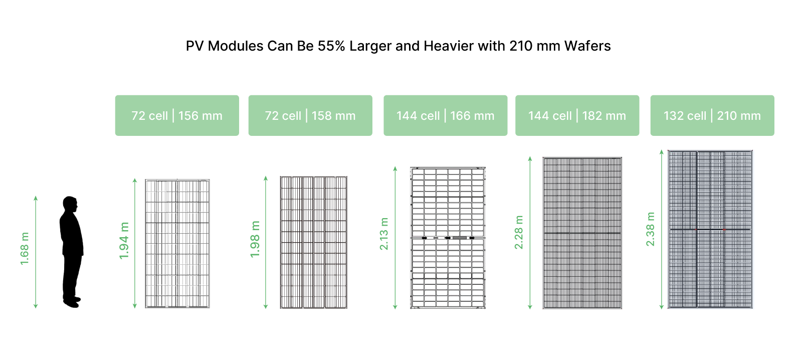
Large-format PV modules, those that are greater than 2100 mm tall, are among the most significant innovations in recent PV module manufacturing history.
They use cells made from larger wafers in order to increase power output per module: a PV system can produce more kilowatt-hours with fewer PV modules, cables, and combiner boxes, which reduces balance-of-system and installation costs.
These products promise lower levelized costs of electricity for solar PV, expanding the potential for project development especially in competitive markets.
Large-format PV modules can also present unique reliability risks:
- Some manufacturers are using thinner glass and/or thinner frames to limit the weight of larger modules, which reduces durability and rigidity.
- Larger PV modules may be subject to more deflection in high wind and snow loads due to their larger surface area.
- Module size impacts thermomechanical stresses caused by daily temperature fluctuations, which can lead to solder joint degradation.
- The silicon wafers within these modules are subjected to increased pressures and mechanical stress due to their larger surface area.
PVEL’s testing demonstrates manufacturers can produce robust large-format PV modules that withstand mechanical stress but using high-quality materials and stringent quality controls is imperative.
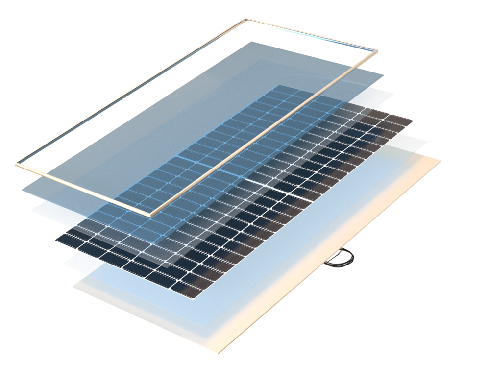
Frame, Frame Adhesive
Glass
Front Encapsulant
Back Encapsulant
Cells, Cell Interconnects
Backsheet
Junction Box Adhesive
Key Takeaways
Click through the key takeaways below.
There were significant failures in this sequence
While 72% of BOMs are Top Performers in MSS, PVEL observed a significant number of failures during this sequence in 2022 Scorecard testing. The most common failure mode was broken glass, not power loss.
81% of large-format PV module designs are Top Performers
More than 80% of modules greater than 2100 mm tall are Top Performers, compared to just 68% of modules less than 2100 mm. This indicates that larger modules can be optimized for mechanical strength.
No glass//glass PV modules suffered cell cracks during MSS
Glass//glass BOMs only failed because of glass breakage, not cell-level damage. Glass//backsheet BOMs were more susceptible to cell cracking, but less susceptible to glass breakage.
Test Procedure
MSS is comprised of four test protocols in sequence: static mechanical load (SML), dynamic mechanical load (DML), thermal cycling, and humidity freeze. The mechanical loading steps create and propagate cracks in susceptible modules, then power loss is induced through the environmental stress of thermal cycling and humidity freeze.
SML comprises three rounds of one hour downward force and one hour upward force at 2,400 Pa. DML comprises 1,000 cycles of oscillating positive-negative loading at ±1,000 Pa. PV modules are then placed in environmental chambers to undergo 50 thermal cycles (-40°C to +85°C) followed by 10 cycles of humidity freeze (+85°C and 85% relative humidity, then a rapid drop to -40°C).
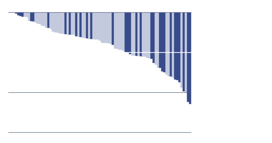
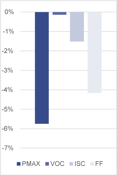
Power Degradation of Each Model Type
Historical MSS
2022 MSS

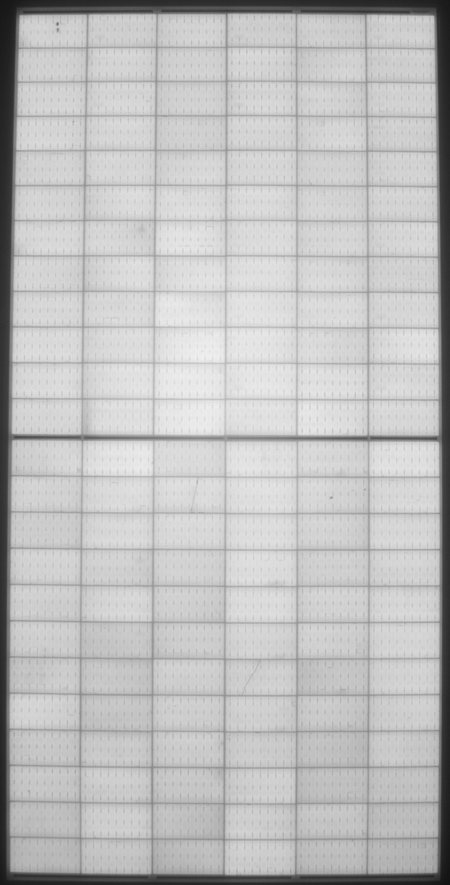
Reading MSS Test Results
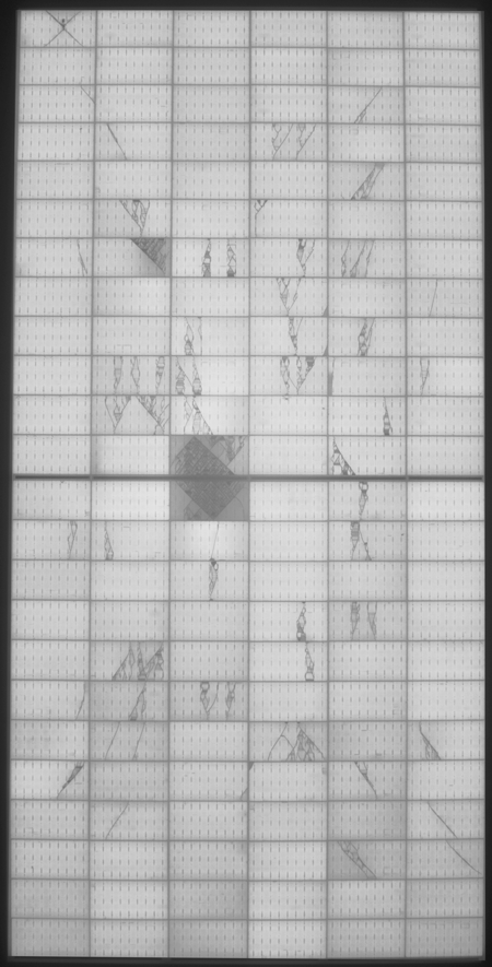
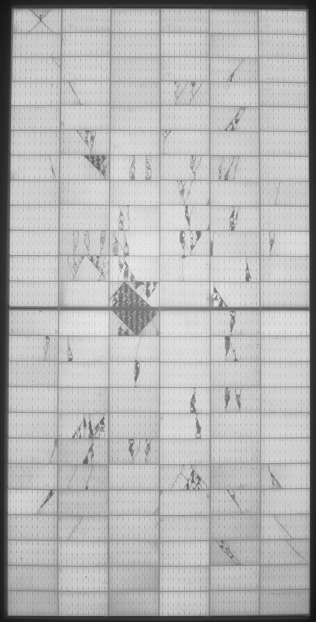
Cell cracks will appear in PV modules that are susceptible to damage from mechanical stress. They appear as dark, discolored, broken lines in EL images. In severe failures, the front or rear glass can break.
PVEL also notes that the cells in glass//glass BOMs are unlikely to suffer damage during MSS as long as the glass remains intact. These designs allow the cells to remain in a neutral plane when the module is under mechanical stress, protecting them from damage.
While some glass//backsheet BOMs provide sufficient cell protection under mechanical stress and others do not, glass//backsheet BOMs are generally less susceptible to glass breakage than glass//glass BOMs.
Prestress
SML
DML
TC50-HF10

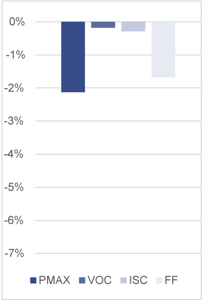
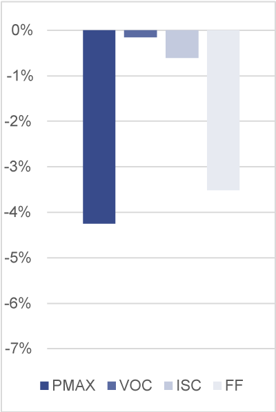
Power Degradation After
SML: 2.1%
DML: 4.3%
TC50+HF10: 5.7%
Deviation from Prestress
Deviation from Prestress
Deviation from Prestress
Prestress
Power Degradation After
SML: 2.1%
DML: 4.3%
TC50+HF10: 5.7%
SML
Deviation from Prestress
DML
Deviation from Prestress
TC50-HF10
Deviation from Prestress
Go beyond model types. Procure PV modules with top-performing bills of materials.
Join PVEL’s downstream partner network.
Sign Up