PVEL’s Thermal Cycling (TC) test assesses a PV module’s ability to withstand changes in temperature. While ambient temperatures vary daily and seasonally in most solar markets, top-performing TC results are most critical in locations where temperatures are much lower at night than during the day, such as desert environments and high-altitude regions.
Thermal Cycling
PV module components expand or contract as temperatures change. The expected amount of expansion or contraction is expressed with a number called a thermal expansion coefficient. Thermal expansion coefficients vary by component, e.g. cells versus cell interconnects. As module temperature changes during the day, this variation in thermal expansion coefficients can create stresses internal to the module that damage components, particularly the solder bonds of cells. Solder bond fatigue can dramatically decrease performance.
Why Testing Matters
PV module warranty claims are a challenge for asset owners, even when there is clear evidence from a class action lawsuit that the supplier is at fault.
When a 100kW commercial PV system in California was underperforming by more than 90% – resulting in losses of >$1,000 per month – the asset owner struggled for nearly a year to receive reimbursement even though his BP Solar modules were subject to a class action lawsuit.
The lawsuit stipulates that BP Solar is only required to replace all modules in systems with >20% failure rates. A replacement inverter that can detect arc faults is provided when PV systems do not meet the 20% threshold.
BP Solar stopped producing PV modules in 2011, so the asset owner’s claim was handled by a third party. They determined that two of >700 modules were eligible for replacement under the lawsuit: only modules with visible hotspots, burn marks and diode failures were covered.
The asset owner pursued a claim based on BP Solar’s performance warranty instead. He learned that:
- Only module-level testing conducted by an independent third party is accepted as evidence of performance loss. String or system-level data are not considered.
- Costs related to the inspection, installation, removal, reinstallation and transportation of PV modules are not covered.
- Financial losses due to system underperformance are not reimbursable.
The asset owner ultimately contacted PVEL for testing. We found that seven of ten randomly selected modules had burn marks and corrosion on the backsheet and showed clear signs of junction box defects. PV module underperformance ranged from 43% to 90%.
PVEL’s thermal cycling test would have identified these defects, but it was not conducted prior to installation.
Manufacturing defects allowed the ingress of moisture into module junction boxes.
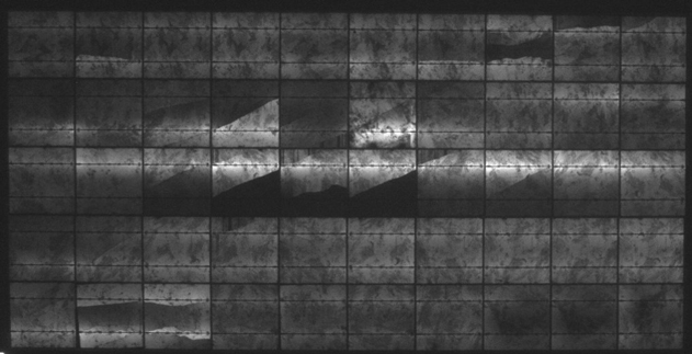
As the dark EL image above indicates, all PV modules tested by PVEL suffered from severe performance loss.
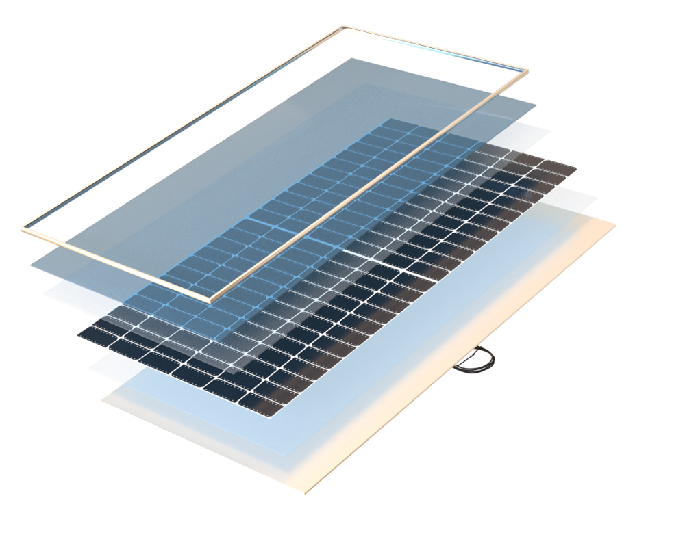
Front Encapsulant
Back Encapsulant
Cells, Cell Interconnects, Flux
Connectors, Bypass Diodes
Key Takeaways
Click through the key takeaways below.
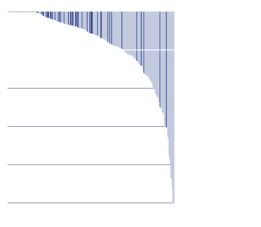
90% of BOMs tested degraded by < 2%
This year’s TC results were the best in PVEL’s history: 90% of BOMs tested degraded by less than 2%, with a median of 0.72% and average of 0.97%.
Over 70% of BOMs tested were multi-busbar (MBB)
BOMs with MBB cell interconnections achieved better test results than older busbar designs on average, indicating that MBB soldering issues can be addressed.
Accelerated testing remains necessary
Two BOMs that passed IEC 61215’s TC 200 requirements ultimately degraded by more than 5% after PVEL’s TC 600 test. This demonstrates that accelerated testing remains necessary for risk mitigation.
Test Procedure
Modules are subjected to extreme temperature swings in an environmental chamber. They are first brought to the very cold temperature of -40°C, then to an extremely hot temperature of 85°C. While the temperature is increased, the modules are subjected to maximum power current providing additional field-relevant stress. The cycle repeats 600 times in total. Characterizations are conducted every 200 cycles.
IEC 61215 testing requires 200 thermal cycles, which does not represent the expected operational lifetime of a PV module in many environments: 25 thermal cycles equates to one year of operation in Chennai, India, but it covers 50 years in Sioux Falls, South Dakota.*
*Bosco, N.S., Silverman, T., Kurtz, S., “Climate Specific Thermomechanical Fatigue of Photovoltaic Module Solder Bonds,” Microelectronics Reliability, March 2016, DOI: 10.1016/j.microrel.2016.03.024
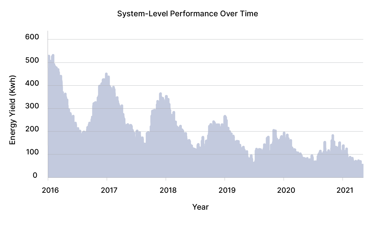
Power Degradation of Each Model Type
Historical TC
2022 TC

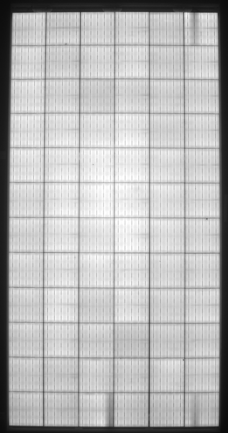
Reading TC Test Results
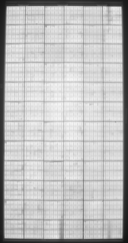
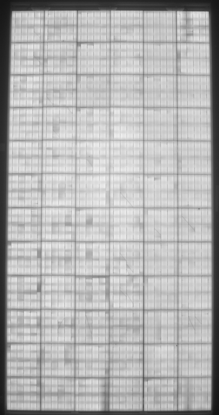
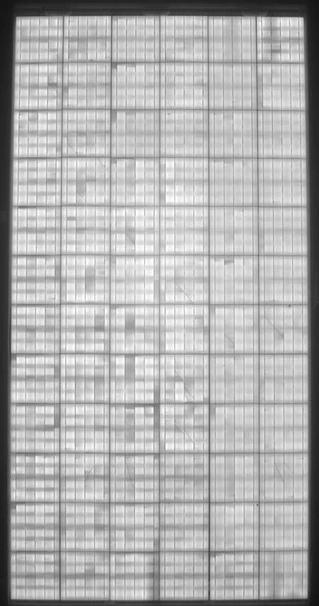
Signs of poor performance are higher degradation rates and as well as cell-level damage that is detected in EL images. In EL images, dark areas along the busbars or the top or bottom of the cell indicate solder bond fatigue.
Prestress
TC200
TC400
TC600
Power Degradation After
200 cycles: 3.5%
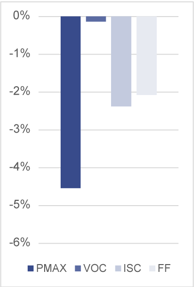
400 cycles: 4.5%
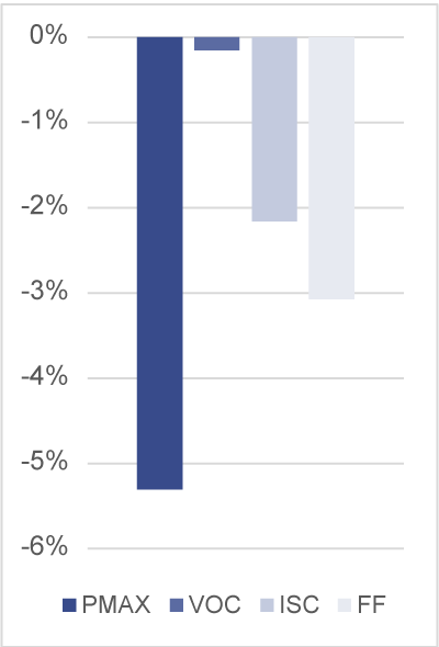
600 cycles: 5.3%
Deviation from Prestress
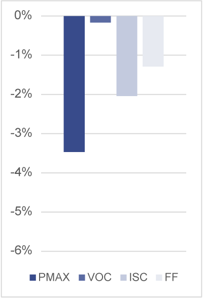
Deviation from Prestress
Deviation from Prestress
Prestress
Power Degradation After
200 cycles: 3.5%
400 cycles: 4.5%
600 cycles: 5.3%
TC200
Deviation from Prestress
TC400
Deviation from Prestress
TC600
Deviation from Prestress
Go beyond model types. Procure PV modules with top-performing bills of materials.
Join PVEL’s downstream partner network.
Sign Up